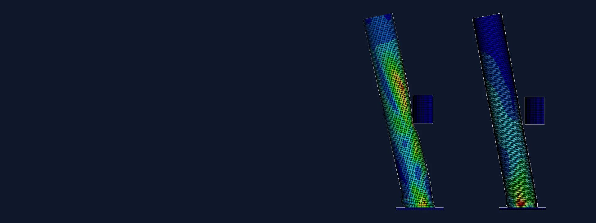
Bollard Impact Simulation: Hollow vs Concrete-Filled Steel Bollard Under Vehicle Strike
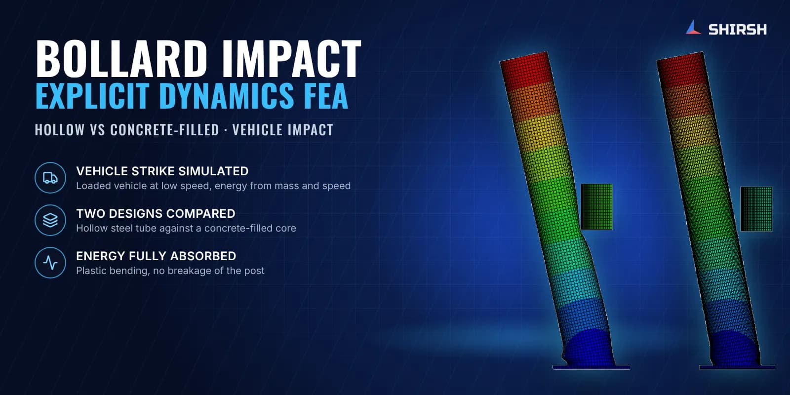
Bollard impact simulation with explicit dynamics FEA. Hollow and concrete-filled steel bollards compared under the same vehicle strike.
Project brief
A steel fabricator that makes safety bollards for a US distributor of facility protection products came to us with a commercial problem. Plastic bollard brands publish impact data for their products. Steel bollards usually come with none, and the distributor's customers had started asking for it. Over the years the bollard's pipe wall had also been thinned to control cost, so the distributor wanted to know what the current design could take and whether filling the tube with concrete would be a sensible upgrade to offer.
Shirsh Technosolutions carried out a bollard impact simulation using explicit dynamics FEA. Two versions of the same bollard were struck by the same vehicle in the model: the standard hollow steel tube, and the same tube filled with a concrete core. The report gave the distributor deformation, stress, plastic strain and energy results for both, in a form that could go straight into customer technical submissions.
What was at risk
A bollard is a short steel post welded to a base plate and anchored to the floor. Its job during a vehicle strike is to stop the vehicle by deforming, not by staying elastic. That makes hand calculation a poor fit. The event lasts a fraction of a second, the steel yields, the tube can kink or ovalise at the point of contact, and the weld at the base takes the bending.
The distributor needed answers to a few plain questions:
Does the current hollow bollard stay in one piece when a loaded vehicle hits it at the specified speed and height?
How much does it bend, and where does the damage concentrate?
What does a concrete core actually change, and is it worth offering as the heavy-duty option?
Can the results be presented as impact performance data, the way competitors present theirs?
Crash testing two configurations on a test track would have taken time and money the product team did not have, and the customer wanted data quickly. Simulation was the practical route.
Solution offered
Defining the impact. The vehicle mass including payload, the speed and the strike height were confirmed with the end user through the client before the load cases were frozen. Impact energy was worked out from mass, speed and impact angle with the kinetic energy formula used in PAS 13 style impact ratings, so the result could be read against how other barrier makers quote their products. The strike was taken head-on at the middle height of the bollard.
Model. The bollard was built in 3D from the client's drawings: the steel pipe, the base plate with its four anchor holes and the pipe-to-plate weld. The concrete-filled version added a solid concrete core inside the tube. The vehicle was represented as a rigid impactor block with the full vehicle mass. Pipe and base plate steels were given nonlinear stress-strain curves taken from the mill test certificates, so yielding and plastic flow follow the actual material rather than a textbook value.
Explicit dynamics set-up.
Nonlinear explicit dynamic analysis, chosen for the short contact event and large plastic deformation.
Hexahedral solid elements with at least two elements through the pipe wall and refinement around the impact zone.
Automatic surface-to-surface contact between impactor and bollard, plus self-contact so the tube cannot pass through itself if it folds.
Pipe-to-plate weld tied, base plate held on a rigid foundation so the result reflects the bollard alone.
The impactor set moving at the impact speed and the run continued until the vehicle had come to rest and the bollard had settled.
What we reported. Stress and displacement plots at regular intervals through the impact for both versions, time histories at monitor points on the pipe and on the base plate, effective plastic strain in the steel, and the energy balance showing the vehicle's kinetic energy being taken up as internal energy of the bollard. A side-by-side comparison of the hollow and concrete-filled designs closed the report.
Common questions
Can FEA replace a physical bollard crash test? Not for certification. A crash test to a named standard is still the formal route. What explicit dynamics FEA gives is reliable comparative data on the actual product geometry and material, quickly and for several design options, which is often what a supplier needs to support a quote or decide which version to take to test.
Does filling a steel bollard with concrete make it stronger? In this study the concrete core made the bollard stiffer. It bent less, resisted local buckling of the tube at the strike point and spread the impact more evenly down the post. The base weld and plate still carry the load in both versions, so the anchorage detail matters whichever option is chosen.
Challenges we overcame
A high-speed contact event with large plastic deformation that static FEA cannot capture
Local kinking of a thin-walled tube at the point of impact
A concrete core and a steel shell that had to work together in the same model
Material behaviour taken from mill test certificates rather than nominal values
Results that had to be usable as product impact data for a customer submission
How we executed
- 1
Confirmed vehicle mass with payload, speed and strike height with the end user through the client
- 2
Calculated the impact energy from mass, speed and impact angle
- 3
Built the 3D model of the pipe, base plate, anchor holes and weld from the client's drawings
- 4
Added the concrete core for the enhanced version and a rigid impactor carrying the vehicle mass
- 5
Assigned nonlinear stress-strain curves to the pipe and base plate steels from their test certificates
- 6
Set up contact, self-contact, the tied weld and the rigid foundation support
- 7
Ran explicit dynamic simulations for the hollow and concrete-filled bollards
- 8
Reported stress, displacement, plastic strain and energy histories and compared the two designs
Project outcome
Both the hollow and the concrete-filled bollard stayed intact under the specified vehicle strike, with no breakage of the post.
The vehicle's kinetic energy was absorbed through plastic bending of the steel, which is how a steel bollard is meant to work.
The hollow bollard bent further and showed visible local deformation at the strike point.
The concrete-filled bollard was stiffer, bent less and spread the impact load more evenly down to the base.
The distributor received impact performance data for its steel bollard and a clear basis for offering the concrete-filled version as a heavier-duty option.
Project gallery
Where this lives
Software used
Related solutions
Industries
At a glance
We apply the same rigour to every engagement
Let us show you what's possible for your product.