Antenna Wind Load CFD and FEA: Structural Check of a Multi-Band Omni Antenna Stack
Antenna wind load CFD in ANSYS Fluent, with surface pressures mapped into ANSYS Mechanical FEA to check every part of a stacked omni antenna.
Project brief
An Indian maker of RF antenna systems had designed a stacked omnidirectional antenna for its customer. The stack carries several radiating elements on one mast, held out by thin rods and an umbrella-type support frame, and it is built from a mix of aluminium and FRP parts. The customer wanted a design check against wind before accepting the product, with pressures, stresses and deflections reported part by part.
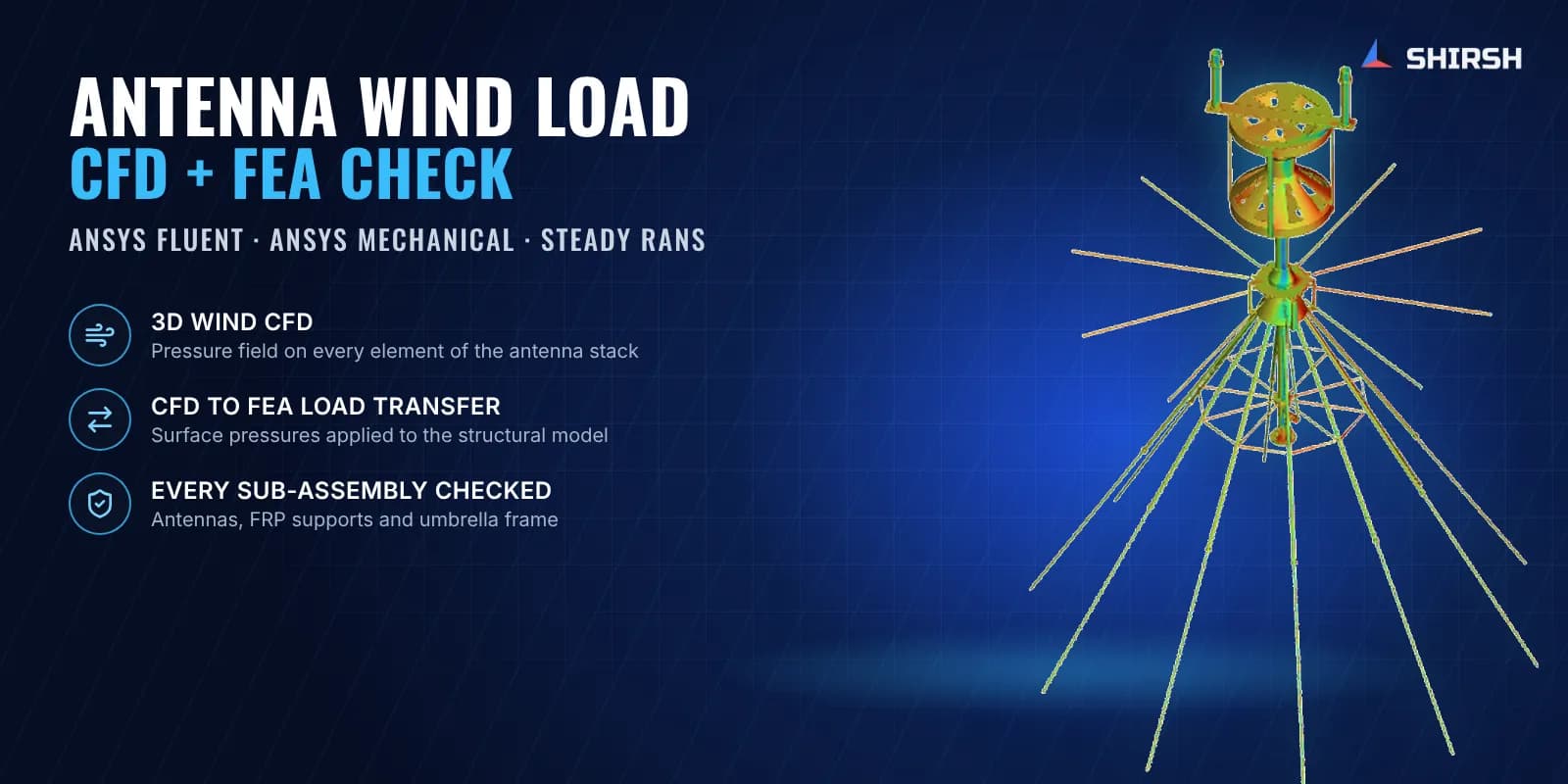
Shirsh Technosolutions carried out an antenna wind load CFD and FEA study. We used ANSYS Fluent to work out how the wind actually loads each element of the stack, then carried those surface pressures into an ANSYS Mechanical structural model and checked every sub-assembly for strength and deflection.
What was at risk
An antenna stack like this is mostly air. It is made of open frames, cones, thin radiating rods and slender FRP tubes, so there is no simple projected area to multiply by a drag coefficient. Some parts sit in the wake of others, the rods meet the wind at many different angles, and the pressure on a cone or a cage changes sign from one face to the next.
Hand calculations with code shape factors would either be very conservative or would miss local suction on parts that look sheltered. The structure is also a mix of materials, with FRP supports carrying metal elements and a hinged umbrella frame at the base, so the weak link is not obvious by inspection.
The client needed:
a realistic pressure distribution on every element of the antenna at the specified wind speed
stress and deflection results for each sub-assembly and for the complete stack
a report they could pass on to their own customer, delivered quickly
Solution offered
Wind modelled around the real geometry. We took the client's 3D model of the antenna stack, cleaned it for analysis and placed it in a large enclosure representing open air. ANSYS Fluent meshing built a poly-hexcore mesh, fine around the thin rods and hubs and coarser in the far field.
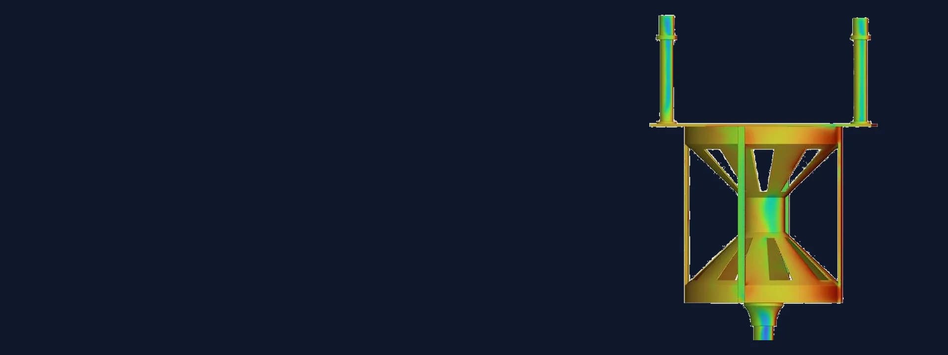
Steady turbulent CFD. The flow was solved as steady, incompressible and turbulent with the k-omega SST model, using a pressure-based solver. The design wind speed was set at the velocity inlet with a pressure outlet downstream. Pressure contours, velocity contours, vectors and streamlines showed which parts take the wind directly and which sit in the wake of others.
Pressures carried into the structure. The surface pressures from CFD were applied region by region to a structural model of the same antenna in ANSYS Mechanical, along with self-weight. The model used second-order shell and solid elements, with each part given its own material: aluminium, FRP, stainless steel, brass and PTFE. Joints were treated as bonded and the stack was fixed at its base mounting points.
Every sub-assembly checked. Deformation and equivalent stress were extracted for the complete structure and separately for the biconical antenna, the shuttlecock antenna, the FRP support assembly, the discone assembly and the support structure with the umbrella mechanism. All of them were within their limits. The highest local stress sat at a bolted connection in a very small region and was identified as a stress concentration, not a general overstress.
Common questions
Why use CFD for antenna wind loads instead of code drag factors? An antenna stack is an open, porous structure where parts shield each other and thin rods meet the wind at different angles. CFD gives the actual pressure on each element, so the structural check uses realistic loads instead of a lumped force on a projected area.
How are CFD pressures used in a structural FEA? The pressure on each surface from the flow solution is applied as a load on the matching faces of the structural model. The FEA then gives stress and deflection in every part, so you can see which element or joint governs the design.
Challenges we overcame
An open, porous antenna stack with no simple projected area for wind load
Thin rods and cones where pressure changes sign from one face to the next
Mixed aluminium, FRP and stainless parts, so the weak link was not obvious
A hinged umbrella support frame at the base carrying the whole stack
A short turnaround set by the client's own commitment to their customer
How we executed
- 1
Reviewed and cleaned the client's 3D model of the antenna stack for analysis
- 2
Built an external flow enclosure and a poly-hexcore CFD mesh in ANSYS Fluent meshing
- 3
Solved steady incompressible turbulent flow with the k-omega SST model at the design wind speed
- 4
Reviewed pressure, velocity and streamline plots to see shielding and wake effects
- 5
Built a second-order shell and solid FEA model with part-wise materials in ANSYS Mechanical
- 6
Applied the CFD surface pressures and self-weight with the stack fixed at its mounting points
- 7
Checked deformation and equivalent stress for each sub-assembly and the full stack
- 8
Reported pressures, stresses and deflections part by part for the client's customer submission
Project outcome
Wind pressures were mapped on every element of the antenna stack, showing which parts take direct wind and which sit in a wake.
All five sub-assemblies and the complete stack were found within their stress limits under the design wind.
The peak local stress was traced to a small region at a bolted connection and identified as a stress concentration.
The client received a part-by-part CFD and FEA report to submit to their own customer.
Project gallery
Where this lives
At a glance
We apply the same rigour to every engagement
Let us show you what's possible for your product.