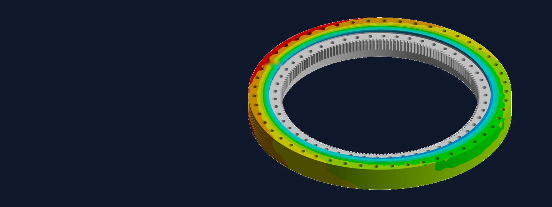
Wire-Race Slewing Bearing FEA Under Transport, Transient and Shock Loads
Slewing bearing FEA in ANSYS for a heavy azimuth-elevation platform: transport, transient, shock and torque cases checked part by part against FOS.
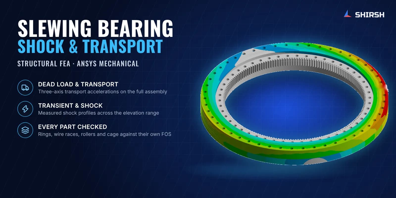
Project brief
A slewing bearing manufacturer had to supply a large wire-race slewing bearing with an internal gear for a heavy azimuth-elevation platform. The platform is moved on a towed chassis, so the bearing sees transport accelerations on the road as well as transient and shock loads in service. The buyer's specification set a minimum factor of safety for each kind of load and asked for the design to be proven by analysis before manufacturing.
Shirsh Technosolutions carried out the slewing bearing FEA in ANSYS Mechanical. We modelled the full bearing as a multi-material assembly, ran every load case in the specification, checked each part against its own allowable and walked the manufacturer's team through the results in a web meeting before issuing the final report.
What was at risk
A wire-race bearing is not one part. Its outer rings are aluminium alloy, the inner gear ring is alloy steel, the wire races are hardened stainless steel, the rollers are bearing steel and the cage is nylon. Each material has a very different strength, so a single stress number for the bearing tells you very little. Every part has to be checked against its own yield strength and the factor of safety that applies to that load type.
The loading is also unusual for a bearing. The platform has an elevating mass and a rotating mass whose centre of gravity moves as the platform elevates. The specification asked for dead load, three-axis transport accelerations, a short-duration transient axial load and moment at a series of elevation angles, three measured shock profiles at several elevations and the normal operating torque. Each combination puts the bearing in a different state of tilt and thrust, and the worst one was not obvious in advance.
The CAD received from the manufacturer also had interferences between parts. These had to be cleaned up before a reliable mesh could be built.
Solution offered
Geometry clean-up and multi-material model. We resolved the interferences in the supplied assembly ourselves, so the analysis could start without another round of CAD revisions. Each component was given its own material: aluminium alloy outer rings, alloy steel gear ring, hardened stainless wire races, bearing steel rollers and a nylon cage.
Solid mesh with quality checks. The full assembly was meshed with hexahedral and tetrahedral solid elements. Element quality, aspect ratio and skewness were checked before any load case was solved.
Platform masses at their real centres of gravity. The elevating and rotating masses were applied as remote masses connected to the race at their specified CG positions, with the upper end of the tolerance band used. For the transient and shock cases the elevating mass was moved to each elevation angle in turn. The inner ring bolting face was fixed to represent the mounting structure.
Every load case in the specification. We ran dead load, positive and negative transport accelerations along all three axes, the transient axial load and moment across the full elevation range, the three measured shock profiles at the key elevations and at the worst transient angle, and the operating torque at the specified slewing speed.
Part-by-part factor of safety check. For each load case the peak equivalent stress in the rings, wire races, rollers and cage was compared with that part's allowable, taken as its yield strength divided by the factor of safety the specification required for that load type. The results were tabulated with a utilisation ratio and a pass or fail status for every part and every case.
Common questions
How do you check a slewing bearing with FEA? Model the rings, races, rolling elements and cage as an assembly with their own materials, apply the payload as remote masses at their centres of gravity, run each specified load case, and compare the stress in each part with its yield strength divided by the required factor of safety.
Which load case usually governs a slewing bearing on a mobile platform? It depends on the mass layout and elevation, which is why every case should be run. On this bearing the vertical transport case loaded the rollers the most, while the transient and shock cases stayed well inside their limits.
Challenges we overcame
Five parts in five different materials, each needing its own allowable and factor of safety
Platform centre of gravity moving with elevation angle, changing the bearing load in every case
Transport, transient, shock and operating torque cases all required by the specification
Measured shock profiles in three axes applied at several elevations
Interferences in the supplied CAD that had to be cleaned up before meshing
Results needed in a form the manufacturer could hand to the buyer for approval
How we executed
- 1
Cleaned up interferences in the supplied bearing assembly
- 2
Assigned materials to the outer rings, gear ring, wire races, rollers and cage
- 3
Built a hexahedral and tetrahedral solid mesh and checked its quality metrics
- 4
Fixed the inner ring bolting face and applied the platform masses as remote masses at their CGs
- 5
Solved dead load and three-axis transport cases
- 6
Swept the transient load across the full elevation range to find the worst angle
- 7
Applied the three measured shock profiles at the key elevations and the worst transient angle
- 8
Ran the operating torque case and checked every part against its required factor of safety
Project outcome
Every load case in the specification passed, with each part within its required factor of safety.
The vertical transport case was identified as the governing case, with the highest stress in the rollers.
Stresses under the transient, shock and operating torque cases were low against their allowables.
The manufacturer received a part-by-part utilisation table it could use with its buyer before manufacturing.
The results were explained in a web meeting, and the same manufacturer has since come back to Shirsh for another slewing bearing analysis.
Project gallery
Where this lives
Software used
Related solutions
Industries
At a glance
We apply the same rigour to every engagement
Let us show you what's possible for your product.