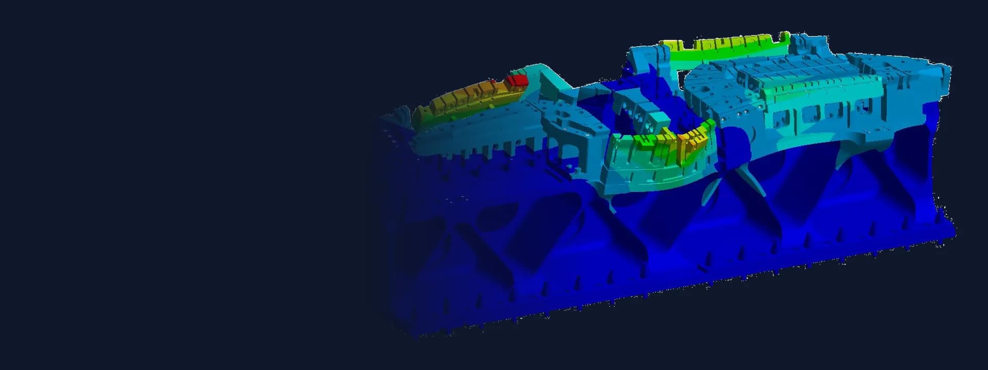
Vibration Welding Tool FEA: Modal and Harmonic Response Analysis of an Upper Tool
Vibration welding tool FEA in ANSYS: modal analysis of a bolted upper tool against the machine's operating band, then harmonic response stress checks.
Project brief
A machine design consultancy was building a linear vibration welding machine for a client in India. The upper tool, the heavy assembly that holds one plastic part and shakes it against the other, had been designed as a stack of machined blocks bolted onto an aluminium body. Before the tool went for manufacture, the team wanted proof that it would not resonate inside the machine's working frequency band.
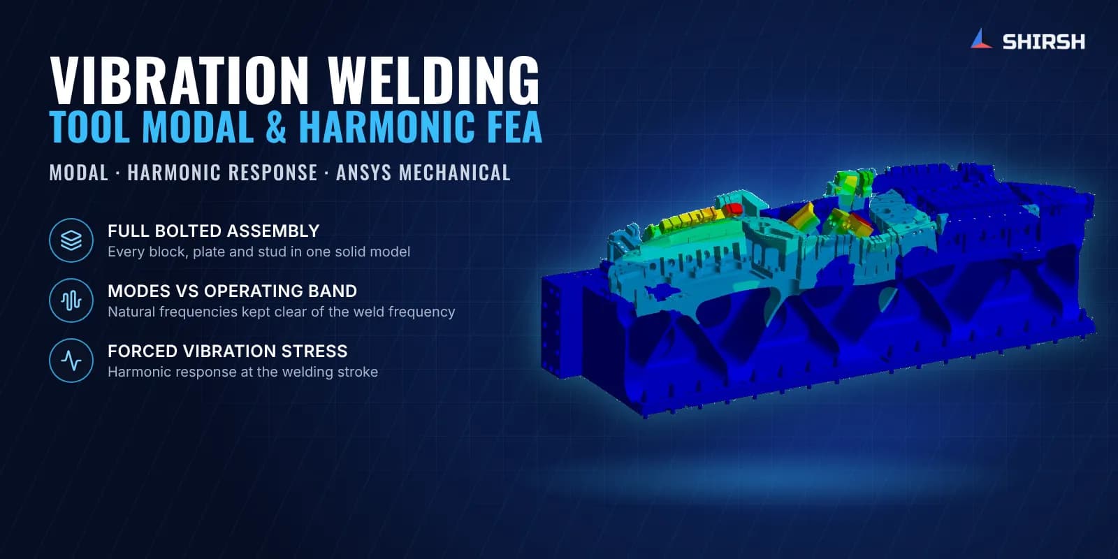
Shirsh Technosolutions ran a vibration welding tool FEA in ANSYS Mechanical. We first carried out a modal analysis of the full bolted assembly to find its natural frequencies and mode shapes, and then followed it with a harmonic response analysis to look at the stress in the tool while it is driven at the welding stroke.
What was at risk
In linear vibration welding, one part is clamped in the upper tool and moved back and forth against the other part under pressure. Friction melts the plastic at the joint, the motion stops, and the joint sets. The upper tool rides on the machine's drive plate and is shaken continuously for every weld cycle.
That makes the tool a dynamic part, not a static fixture. If any of its natural frequencies falls in or near the operating band, the tool can resonate. Amplitudes then grow, bolts loosen, blocks fret against each other and cracks start at the corners. A tool built from many separate blocks is hard to judge by eye, because each block, plate and stud adds its own stiffness and mass, and local modes can hide in small overhanging pieces.
The client needed:
the natural frequencies and mode shapes of the complete upper tool as it is mounted in the machine
a clear answer on whether any mode sits close to the operating band
the stress the tool sees when it is driven at the welding stroke, delivered quickly because the machine handover date was fixed
Solution offered
CAD made ready for analysis. We reviewed the client's 3D CAD of the upper tool before meshing. Some bolts overlapped their holes in the model, which a finite element mesh cannot accept, so we flagged the interferences and the client sent a clean revision. Materials came from the client's drawings: alloy and carbon steel blocks, stainless parts and an aluminium body.
One model of the whole assembly. Every block, plate and stud was kept in a single solid model and meshed with quadratic tetrahedral elements in ANSYS Mechanical. Element size was chosen from the smallest features of the tool, which made it a very large model to solve. The contacts between parts were included so the stiffness of the bolted stack came from the real joint layout.
Boundary conditions that match the machine. The top face of the tool rests on the machine drive plate, so it was modelled as a frictionless support. The stud locations where the tool is bolted to the drive plate were fixed. Self-weight was taken from the material densities.
Modal analysis against the operating band. The block Lanczos solver extracted the first ten modes. We checked each mode shape for local motion of the tooling blocks and read the mass participation factors in all six directions, so the client could see which modes would actually be excited by a stroke along the welding axis. The fundamental frequency came out well above the machine's operating band, with all ten modes clear of it, so the upper tool was reported safe for dynamic operation under normal working conditions.
Harmonic response at the welding stroke. The client then asked for the stress generated in the tool during vibration. We extended the same model into a harmonic response analysis. The welding stroke was applied as a base excitation along the welding axis, converted from displacement amplitude to acceleration at each frequency, and swept in steps across the operating band. Stress results and an animation of the tool's forced motion were delivered to the client for review.
Common questions
Why run a modal analysis on a vibration welding tool? The tool is shaken at a fixed frequency for every weld. If one of its natural frequencies is close to that frequency, it resonates, and amplitudes and stresses climb far above what the drive was meant to produce. A modal analysis shows how much margin there is before the tool is cut.
What does a harmonic response analysis add after a modal check? Modal analysis tells you where the resonances are. Harmonic response applies the actual stroke at the operating frequencies and gives the steady-state deformation and stress, so you can see how hard each block and bolt is working in normal welding.
Challenges we overcame
A tool built from many bolted blocks, where local modes can hide in small overhanging pieces
CAD interferences between bolts and holes that had to be cleared before meshing
A very large solid model, needed to capture the smallest features of the tool
Mounting conditions represented as they are in the machine, resting face plus bolted studs
A tight handover date set by the client's own commitment to their customer
How we executed
- 1
Reviewed the client's 3D CAD and flagged bolt and hole interferences for a clean revision
- 2
Assigned steel, stainless and aluminium properties from the client's material drawings
- 3
Meshed the full bolted assembly with quadratic tetrahedral elements in ANSYS Mechanical
- 4
Modelled the top face resting on the drive plate and fixed the stud locations
- 5
Extracted the first ten natural frequencies and mode shapes with the block Lanczos solver
- 6
Read mass participation factors in all directions to see which modes the stroke would excite
- 7
Compared every mode against the machine's operating band and reported the margin
- 8
Ran a harmonic response analysis with the welding stroke as base excitation across the operating band
Project outcome
All ten natural frequencies of the upper tool were found well above the machine's operating band, so no resonance is expected in normal welding.
The upper tool was reported safe for dynamic operation under normal working conditions.
Mode shapes and mass participation showed which tooling blocks move most, useful for any later change to the tool.
The client received a modal analysis report, followed by harmonic response stress results and an animation of the tool's forced motion.
Project gallery
Where this lives
Software used
Related solutions
Industries
At a glance
We apply the same rigour to every engagement
Let us show you what's possible for your product.