
Telescopic Sliding Gate Wind Load FEA to IS 875 Part 3
Telescopic sliding gate wind load FEA to IS 875-3 and IS 800: leaf, posts, rollers, wheels, stops and side supports checked before fabrication.
Project brief
A gate and door automation manufacturer had won an order for a very wide double-leaf telescopic sliding gate at a large industrial facility. The gate opens a long clear span, the leaves are tall and open-framed, and the site sits in a high wind zone. Before fabrication, the buyer wanted proof that the gate would stay standing and keep running in a design storm.
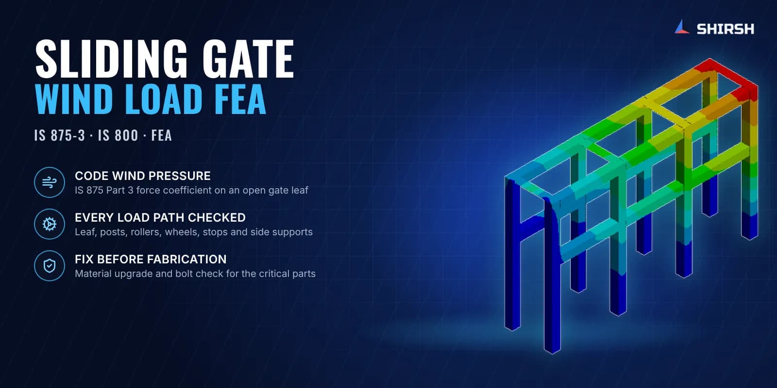
Shirsh Technosolutions carried out a wind load FEA of the telescopic sliding gate to IS 875 Part 3 and IS 800. We worked out the code wind pressure on the open leaf, then modelled and checked each part that carries that load to the ground: the leaf frame, the steel posts, the wheel carriages, three sets of guide rollers, the limit stops and the side supports. Wheel bolts were checked by hand. The first round flagged the pinned side support as the weak link, so the manufacturer could fix it on the drawing board.
What was at risk
A telescopic gate is not one structure. Each leaf runs on wheel carriages along a bottom track, is held upright by guide rollers on posts, and is braced sideways by a support arm when closed. Wind on the leaf travels through all of these parts in turn, and the weakest one decides whether the gate survives. A check on the leaf frame alone would miss most of the risk.
Wind load on an open gate is also easy to get wrong. The leaf is a framed grille, not a solid wall, so the force depends on how much of the frame area is actually filled. Too low a pressure hides a problem, and too high a pressure adds steel the gate has to drag along on every opening.
The client needed an answer while the drawings were still open for change, and with stresses and deflections compared against clear limits that the buyer's engineers would accept.
Solution offered
Code wind pressure on an open leaf. Design wind speed was built up from the basic wind speed of the site zone with the IS 875 Part 3 risk, terrain-height and topography factors. The leaf was treated as a single open frame, and the force coefficient was picked from the code table for its solidity ratio. This gave one design pressure applied normal to the leaf.
Part-by-part finite element models. The leaf frame and the post frames were modelled with shell and beam elements, and the cast and machined parts (wheel carriages, roller sets, stops and supports) with higher-order solid elements. Welds were modelled as bonded contacts. Reactions were taken from the leaf model and passed on to each support part in proportion to how many of them share the load, so every part saw the force it actually carries.
Strength and stiffness limits. Von Mises and shear stresses in the steel parts were compared with the yield strength of the specified steel, and the nylon roller tyres were checked against their own material limit. Leaf and post deflection was checked against the IS 800 span-over-180 limit for a cantilever-type element.
Stops and side supports. The limit stop was checked for the full leaf running into it. The side supports, which hold the closed leaf against wind, were checked both as a pinned arm and with a support wheel.
Bolted joints. The wheel carriage bolts were checked by hand for the combined wind and dead load reactions from the FEA, against the breaking load of the specified high-strength fine-pitch bolt.
A clear fix for the weak part. The revised analysis showed the foldable pinned side support as the most stressed part. Instead of a blanket "increase sizes", we told the client what yield strength the support material needed, so the change was one line on the drawing.
Common questions
How is wind load calculated for a sliding gate in India? Take the basic wind speed for the site from IS 875 Part 3, apply the risk, terrain-height and topography factors to get the design wind speed and pressure, then multiply by the force coefficient for a single open frame based on the gate leaf's solidity ratio.
Which parts of a sliding gate fail first in high wind? Usually not the leaf. The guide rollers, wheel carriages, end stops and side supports take the leaf reaction at a few small points, so they see the highest stresses. Each one should be checked with the load it actually carries.
Challenges we overcame
A very wide double-leaf gate in a high wind zone
Open grille leaf, where the force coefficient depends on solidity
Wind load passing through many small parts: wheels, rollers, stops and supports
Steel and nylon parts with very different strength limits
Bolted wheel carriages under combined dead and wind load
Answer needed while drawings could still change
How we executed
- 1
Reviewed the gate GA and part drawings from the manufacturer
- 2
Worked out design wind speed, pressure and open-frame force coefficient to IS 875 Part 3
- 3
Built finite element models of the leaf, posts, wheel carriages, roller sets, stops and side supports
- 4
Applied wind pressure to the leaf and distributed its reactions to the support parts
- 5
Checked stresses against material yield and deflections against the IS 800 limit
- 6
Checked the wheel carriage bolts by hand for the FEA reactions
- 7
Re-analysed the foldable pinned side support after the first review
- 8
Issued the report with a material recommendation for the critical part
Project outcome
Leaf, posts, wheel carriages, guide rollers and limit stops stayed within the yield strength of their materials under the design wind.
Leaf and post deflections stayed inside the IS 800 limit.
Wheel carriage bolts showed a clear margin over the dynamic bolt load.
The foldable pinned side support was found to be the critical part, and a higher-strength steel was recommended for it.
The manufacturer got a code-referenced report for its buyer before fabrication.
Project gallery
Where this lives
Software used
Related solutions
Industries
At a glance
We apply the same rigour to every engagement
Let us show you what's possible for your product.