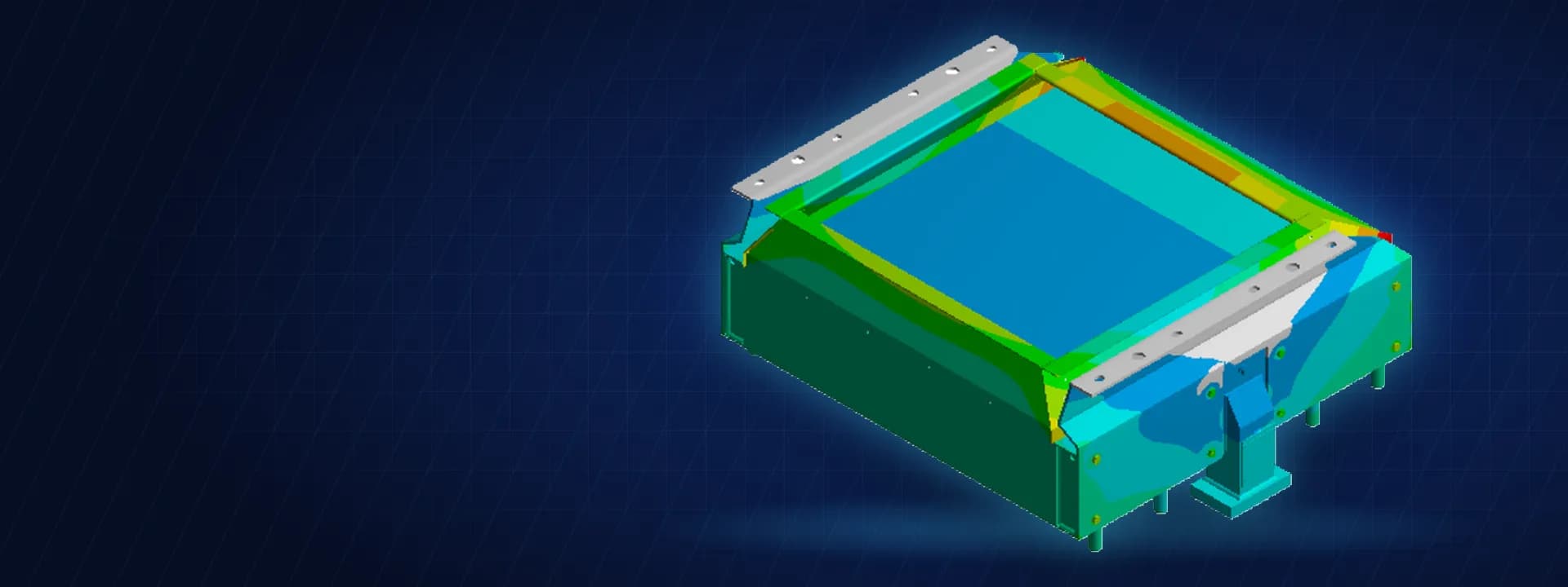
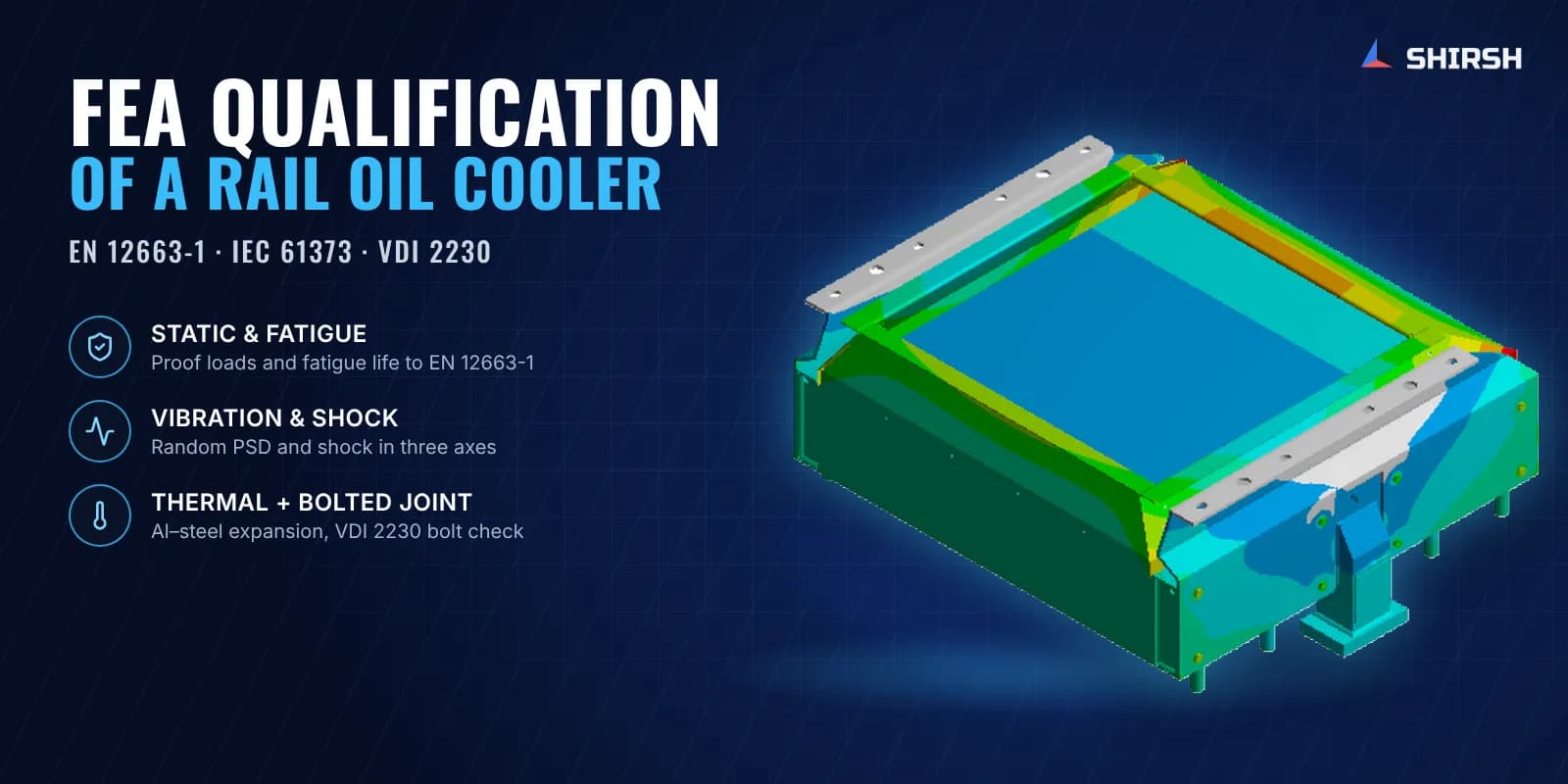
FEA Qualification of a Locomotive Transformer Oil Cooler to EN 12663 and IEC 61373
Static, fatigue, random vibration and shock FEA of a rail transformer oil cooler, qualified to EN 12663-1 and IEC 61373 by analysis.
Project brief
A heat exchanger manufacturer supplying transformer oil coolers for electric locomotives had to show the locomotive builder that the cooler and its fixings would last the life of the vehicle. The qualification route was EN 12663-1 for static and fatigue loads and IEC 61373 for random vibration and shock.
Shirsh Technosolutions took on the complete qualification by FEA in ANSYS Mechanical, from model build through to a report written for the builder's design review. Doing it by analysis gave the client stresses and margins for every component, which a shaker test on its own does not give.
What was at risk
The cooler hangs from the vehicle body on bolted steel brackets. Its brazed aluminium core is joined to stainless steel brackets and cowls and to aluminium headers and bosses, so one assembly mixes several alloys, each with its own allowable stress and fatigue behaviour. The aluminium core is also much softer than the steel around it.
The builder wanted answers component by component:
whether any part would yield under the EN 12663-1 proof loads
whether welds and parent metal would reach the required fatigue life under service accelerations
whether any natural frequency fell inside the rail vibration band and amplified the response
whether the bolts joining the aluminium core to the steel brackets would hold once the two metals expand differently with temperature
Solution offered
We built a detailed shell and solid FE model of the full assembly. Fixings sat at the real mounting points on the vehicle body, and the bolts were modelled with pretension so their forces came straight out of the analysis. Mesh quality was checked before any result was used.
The study covered every load set the two standards ask for:
Static proof: longitudinal, lateral and vertical proof loads with dead weight and pipe loads, checked with separate safety factors for parent metal and welds.
Fatigue: EN 12663-1 service acceleration states combined into stress ranges and assessed against EN 1993 and EN 1999 S-N curves.
Modal: natural frequencies and mode shapes, to find the modes inside the excitation band.
Random vibration: IEC 61373 functional and simulated long-life inputs in all three axes.
Shock: transient analysis with the IEC 61373 shock pulse in each axis.
Thermal: the operating temperature range, to capture differential expansion between aluminium and steel and its effect on bolt loads.
The bolted joint was checked separately to VDI 2230, including preload scatter, thread friction and surface pressure under the bolt head.
Common questions
Can FEA replace shaker testing under IEC 61373? FEA can screen the design and find weak spots before a prototype exists. Whether it can stand in for a physical test is up to the vehicle builder or the approving body.
Why check aluminium and steel joints for temperature? Aluminium expands a good deal more than stainless steel for the same temperature change. That difference loads the bolts and bracket holes even when the vehicle is standing still.
Challenges we overcame
Several alloys with very different allowables in one assembly, including a soft brazed aluminium core
Different safety factors for welds and parent metal, applied to the right regions of the model
A large set of fatigue stress ranges processed against EN 1993 and EN 1999 S-N curves
Modes inside the rail excitation band, so the random vibration response had to be resolved properly
Bolt loads from differential thermal expansion between the aluminium core and steel brackets
Presenting results in a form the locomotive builder's design review could work with
How we executed
- 1
Reviewed the GA, bill of materials and mass data, and set up the vehicle axes and mounting points
- 2
Built a shell and solid FE model with pretensioned bolts and checked mesh quality
- 3
Ran the EN 12663-1 static proof load cases with separate factors for welds and parent metal
- 4
Built the service stress ranges and assessed fatigue life to EN 1993 and EN 1999
- 5
Ran modal analysis, then IEC 61373 functional and long-life random vibration in three axes
- 6
Ran transient shock analysis in three axes
- 7
Ran the thermal case and checked the core-to-bracket bolts to VDI 2230
- 8
Issued the qualification report and supported the client through the design review
Project outcome
Every component met the EN 12663-1 static limits, with clear margin on the brazed aluminium core and the steel brackets.
Weld stresses stayed within limits even with the stricter weld safety factor.
The core-to-bracket bolts passed VDI 2230 with margin on both proof strength and surface pressure.
Shock and random vibration stresses stayed within the allowable limits, and fatigue was assessed for the full design life.
The report answered the builder's design review comments and gave them a component-by-component analysis basis for the design.
Project gallery
Where this lives
Software used
Related solutions
Industries
At a glance
We apply the same rigour to every engagement
Let us show you what's possible for your product.