Gate Valve CFD: Flow Coefficient (Cv) of a Large Double-Reduced-Bore Valve
Gate valve CFD in ANSYS Fluent to find full-open Cv and Kv, with standard 2D and 6D pipe runs and a double-reduced seat bore.
Project brief
A valve manufacturer needed the full-open flow coefficient of a large, high-pressure-class gate valve for its datasheet. The valve has a double reduction in the bore from the end connection to the seat, and the company makes the same design in other sizes, so it wanted a number it could trust before taking the range further.
Shirsh Technosolutions ran gate valve CFD in ANSYS Fluent on the full 3D flow path and worked out Cv and Kv at a fixed pressure difference. Before the large valve, the client's R&D team gave Shirsh a smaller sample valve to see how the method and the reporting would look.
What was at risk
On a full-bore gate valve the flow coefficient is often taken from a simple formula or from an older, similar size. That gets harder once the bore steps down twice before the seat. Each step contracts the flow, the jet leaves the seat faster than it entered, and the pipe downstream has to recover that pressure. The open gate cavity above the bore also takes part in the flow, and none of this shows up in a hand estimate.
Testing a valve of this size on a flow rig means a big pump, long pipe runs and a lot of water, so the client wanted a simulation that it could read the same way as a test. The questions were simple:
what is the full-open Cv and Kv of the valve with its reduced bore
where is the pressure lost, at the steps, at the seat or in the pipe after it
will the result follow the pipe lengths the flow-test standard asks for, so it can sit next to measured data
Solution offered
A sample valve first. The R&D team sent a small gate valve as a trial. Shirsh modelled it, estimated Cv and Kv and sent a short report. The client then asked for the inlet pipe to start two pipe diameters upstream and the outlet to run six diameters downstream, which is what its flow-test standard calls for. Shirsh rebuilt the domain to that layout, re-ran the case and issued a revised report the same day, and the client's R&D head accepted it.
The large valve with the double reduction. For the main job the client supplied the 3D model of the large valve. Shirsh checked the geometry before meshing and pointed out that the double step could not be seen in the first file. The client sent a corrected model, and that one was used.
Fluid domain and mesh. The wetted volume of the valve was extracted with the gate fully open and joined to pipe runs of two diameters upstream and six downstream. A poly-hexcore mesh was built in Fluent Meshing, finer through the reduced bore and the seat, and the cell quality histogram was checked before solving.
Solver set-up. The case was solved as steady, incompressible, turbulent water flow with the pressure-based coupled solver, the k-omega SST turbulence model and second-order schemes for pressure and momentum. A pressure inlet and a pressure outlet held a constant pressure difference across the valve and pipe, so the flow rate came out of the solution.
From flow to Cv and Kv. The volume flow at that pressure difference was converted to Cv with the standard liquid sizing relation, using the specific gravity of water, and Kv was taken from Cv. Velocity and pressure were plotted on the central plane and on five cross-sections along the flow, and the residual history was used to confirm convergence.
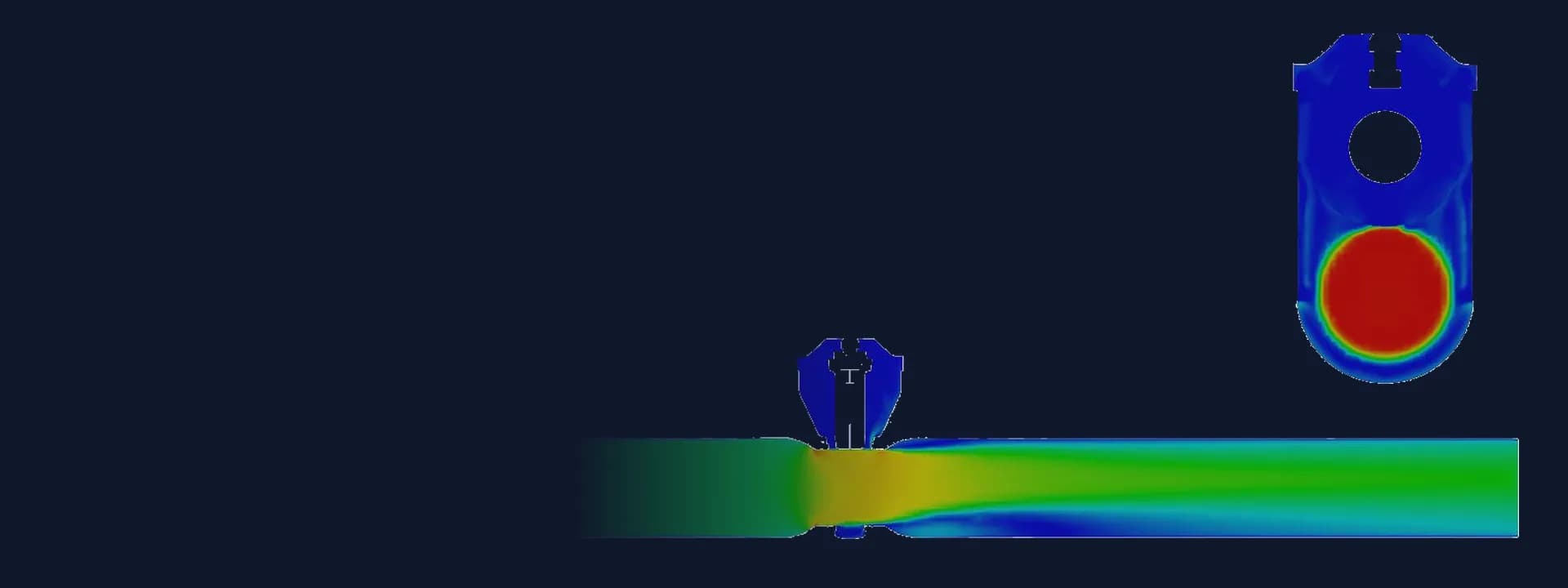
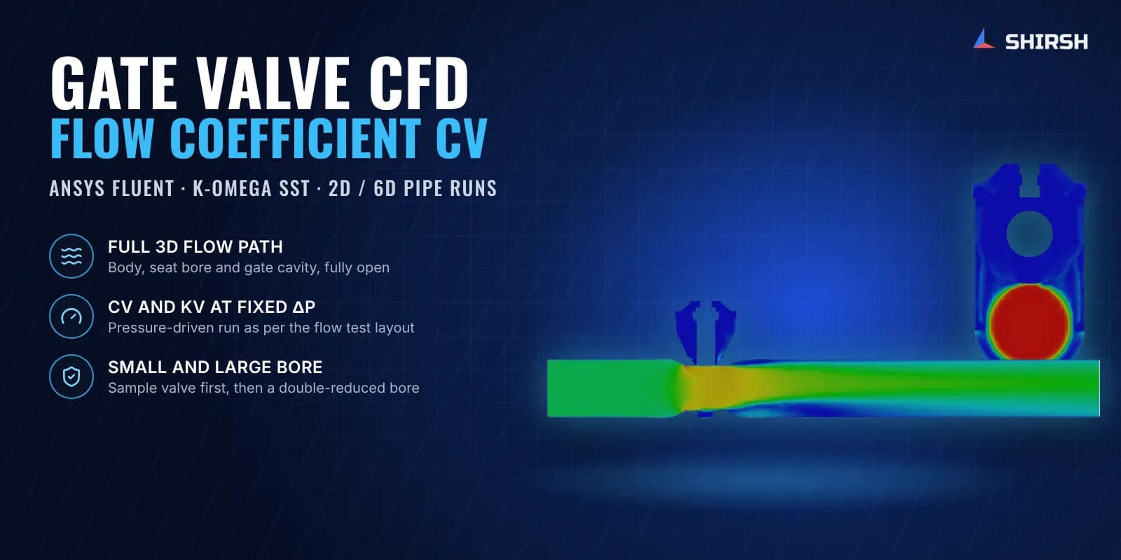
What the contours showed. Velocity rises sharply through the stepped bore and peaks at the seat, the gate cavity stays almost stagnant, and a low-velocity zone forms along the bottom of the pipe just after the seat before the flow settles. The pressure contours show the sharpest drop across the stepped section and the seat, with part of it recovered in the pipe downstream.
Common questions
How is the Cv of a gate valve calculated with CFD? The full-open valve is modelled with straight pipe on both sides and a fixed pressure drop is applied between inlet and outlet. CFD gives the volume flow at that drop, and Cv follows from Q x sqrt(SG / dP) in US gallons per minute and psi. Kv is the metric equivalent.
Why do the 2D upstream and 6D downstream pipe lengths matter in valve CFD? Flow coefficients are measured with pressure taps a set number of pipe diameters before and after the valve, and the jet leaving the seat needs some pipe length to recover. Matching the same lengths in the CFD model makes the simulated Cv comparable with a rig test and with catalogue data.
Challenges we overcame
A double reduction in the bore that a simple full-bore Cv estimate does not capture
A valve too large to flow-test easily, so the CFD had to be read like a rig result
Pipe lengths changed mid-way to the 2D upstream and 6D downstream layout of the client's flow-test standard
A first CAD file that did not show the stepped bore, caught before meshing
Flow through the open gate cavity as well as the main bore
How we executed
- 1
Ran a smaller sample gate valve and reported full-open Cv and Kv
- 2
Rebuilt the sample domain to the client's 2D upstream and 6D downstream pipe layout and re-issued the report
- 3
Received the 3D model of the large valve and checked the stepped bore before meshing
- 4
Extracted the full-open fluid volume and joined the standard pipe runs
- 5
Generated a poly-hexcore mesh in Fluent Meshing and checked cell quality
- 6
Solved steady incompressible turbulent flow with k-omega SST at a fixed pressure difference
- 7
Converted the computed flow to Cv and Kv and checked convergence from the residuals
- 8
Issued the report with velocity and pressure contours on the central plane and five sections along the flow
Project outcome
The client received the full-open Cv and Kv of the large double-reduced-bore gate valve from a converged 3D CFD model.
The sample valve study was accepted by the client's R&D head after it was re-run to the standard pipe layout.
Velocity and pressure contours showed the design team where the flow speeds up and where the pressure drops inside the valve.
The same set-up can be reused for the other sizes of this valve range.
Project gallery
Where this lives
Software used
Related solutions
Industries
At a glance
We apply the same rigour to every engagement
Let us show you what's possible for your product.