Axial Fan Rotor Dynamics FEA: Critical Speeds from a Campbell Diagram
Axial fan rotor dynamics FEA in ANSYS Mechanical: belt-loaded shaft, prestressed modal sweep and Campbell diagram to find critical speeds of a VFD fan.
Project brief
An HVAC engineering company was putting a belt-driven axial fan into a supply-air system and planned to run it on a variable frequency drive. Before commissioning it wanted to know whether any critical speed of the fan rotor sat inside the speed band the drive would cover, because running a fan on top of a critical speed is a quick route to vibration, bearing wear and noise complaints.
Shirsh Technosolutions carried out an axial fan rotor dynamics FEA in ANSYS Mechanical on the client's own 3D assembly. We loaded the shaft with the belt pull and self weight, ran a prestressed modal analysis with the rotor spinning across its speed range, built the Campbell diagram and handed over a table of critical speeds and bearing reactions, so the client knew exactly which speeds the drive should stay away from.
What was at risk
On a VFD the fan does not run at one speed. It can sit anywhere inside the drive's range for long periods, so every natural frequency of the rotor has to be checked against every speed it may run at, not only the nameplate speed.
A plain modal check of the stationary fan would not answer this. Once the rotor spins, gyroscopic effects split each bending mode into forward and backward whirl, and their frequencies drift as the speed changes. The belt also pulls the shaft sideways, so the rotor is pre-loaded before it even turns.
The client needed:
a rotor model that carried the real shaft, hub and blade materials and the belt load from the pulley
natural frequencies tracked across the full operating speed range, with whirl direction and stability for each mode
a clear list of critical speeds it could use while setting up the drive
bearing reactions at operating speed for the bearing and support check
Solution offered
Model built from the client's assembly. The client shared the fan assembly as a 3D model along with the pulley torque and the materials: an alloy steel shaft, polymer blades and a die-cast aluminium impeller hub. In ANSYS Mechanical the shaft was defined as a beam element carrying the rotating hub and blades, and the two bearings were modelled as stiff bearing connections to ground.
Static step with real loads. The belt pull was applied at the pulley end of the shaft and gravity on the whole rotor. This structural step showed how the shaft bends under the belt load and gave the pre-stress for the dynamic step.
Prestressed modal and Campbell diagram. A prestressed modal analysis was then run with rotational velocity applied in steps from near standstill to the top of the operating range, so that the whirl direction and stability of each mode were captured. ANSYS Mechanical's rotordynamics tools tracked each mode across the speeds and plotted the Campbell diagram, natural frequency against rotor speed, with the excitation line and the operating range marked on it.
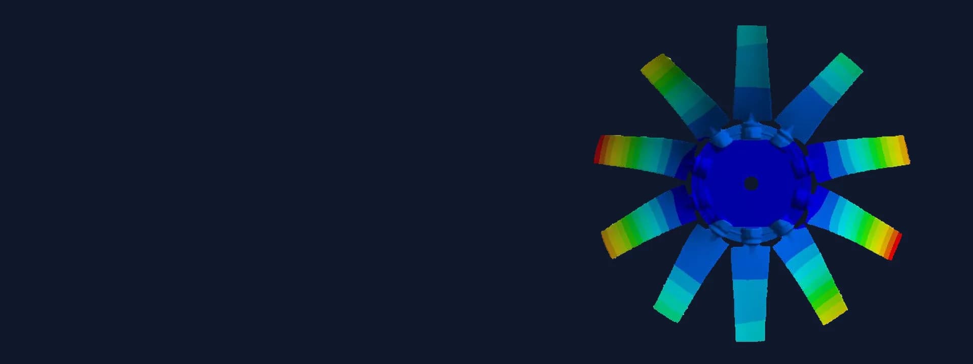
Results read for the client. The report sets out the mode shapes at full operating speed, the Campbell diagram, a table of critical speeds with whirl direction and stability for every mode, and the elastic bearing reactions for each mode at full speed. The report was updated after the client's review before the final issue.
Common questions
What is a Campbell diagram used for in fan design? It plots each natural frequency of a rotor against its running speed. Where a frequency line crosses the excitation line, the fan has a critical speed, so the diagram shows at a glance which speeds are safe to run at and which should be skipped on the drive.
Why is a normal modal analysis not enough for a VFD-driven fan? A stationary modal analysis ignores spin. In a rotating rotor, gyroscopic effects split modes into forward and backward whirl and shift their frequencies with speed, and a VFD can hold the fan at any speed in its range, so the frequencies have to be tracked across that whole range.
Challenges we overcame
A fan that can run anywhere inside a VFD speed range, so every speed had to be checked
Gyroscopic effects that split and shift the rotor modes as speed changes
A sideways belt pull that pre-loads the shaft before it turns
Three very different materials in one rotor: alloy steel shaft, polymer blades and die-cast aluminium hub
Many closely spaced modes that had to be tracked one by one across the speed sweep
How we executed
- 1
Received the fan assembly model, pulley torque, material list and the drive's operating range from the client
- 2
Simplified the assembly and defined the shaft as a beam element carrying the hub and blades
- 3
Modelled the two bearings as stiff connections to ground
- 4
Applied the belt pull at the pulley end and gravity on the full rotor in a static step
- 5
Ran a prestressed modal analysis with rotational velocity stepped across the operating range
- 6
Built the Campbell diagram and read the critical speeds, whirl direction and stability of each mode
- 7
Extracted the elastic bearing reactions for each mode at full operating speed
- 8
Updated the report after the client's review and issued the final Campbell diagram, critical speed table and bearing reactions
Project outcome
A Campbell diagram for the fan rotor across its full operating speed range, with the excitation line and the operating band marked.
A table of critical speeds with whirl direction and stability for every mode, showing a cluster of critical speeds at the lower end of the operating range.
Mode shapes at full speed and bearing reactions for each mode, for the bearing and support check.
A clear list of speeds for the client to keep clear of while setting up the variable frequency drive.
Project gallery
Where this lives
Software used
Related solutions
Industries
At a glance
We apply the same rigour to every engagement
Let us show you what's possible for your product.