Cyclone Separator (device) is a method of removing particulates from an air, gas or liquid stream, without the use of filters, through vortex separation. The objective of this project was to check the design of cyclone separators ( in total three separators working in tandem, for various load cases as mentioned in the objective of analysis.
The objective of the Analysis
- To carry out analysis using the Finite Element (FE) approach while considering the procedures and rules for stress classification as presented in the ASME Code, Section VIII, Div. 2 – Part 5.
- The work is to evaluate the mechanical and thermal stresses at critical locations of the cyclone.
For the above analysis, we have chosen the thermo-Structural analysis as the temperature of operation was in the range of 500C.
The work is to evaluate the mechanical stresses at critical locations of the cyclone at high temperatures. The code of construction is Section VIII, Division 1, of the ASME Code, the allowable stress values are from Section VIII, Div 1, of the ASME Code. The analysis was performed as per clause U2-g of Section VIII, Div 1 using the Finite Element (FE) approach while considering the procedures and rules for stress classification as presented in the ASME Code, Section VIII, Div. 2 – Part 5, Stress distribution is calculated with a 3D finite element model generated by ANSYS Mechanical FEA Solver.
Model and analysis tool: Ansys 2020R1 software was used to generate the 3D FE model of the cyclones. The model includes the gas inlet and outlet connected with the main body. The temperatures and external loads are also applied to the model to qualify the cyclone for mechanical stress at high temperatures.
Analysis Condition:
- The cyclone is typically subjected to internal pressure, thermal loads, Nozzle loads and external loads (wind, seismic) if present any.
- The internal pressure of 1.0787 MPa applied to all model internal faces and thermal loads are the design conditions. Nozzle Loads are also applicable at the inlet and outlet of the Separator Set.
- Thermal FE analysis and the temperature distribution (thermal) from FEA is applied as loads for the Strength assessment static cases.
- Supports are provided at the lugs.
Results and Discussion
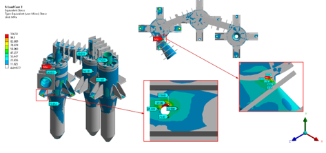
Stress results in a total of three (3) load cases –
- load case 1:Pe(External Pressure)+D(Dead load)+ E(Emergency Load)+T(self- restrained load);
- load case 2: Pe(External Pressure)+D(Dead load)+ E(Emergency Load)+T(self- restrained load) + EX (Seismic Load);
- load case 3: Pe(External Pressure)+D(Dead load)+ E(Emergency Load)+T(self- restrained load)+ EZ (Seismic Load) – were reported in this study. Also, the stress linearization has been performed at the critical locations with a total of 15 linearization lines to qualify the high-stress value.
- The results of the FE analysis indicate that calculated stresses are within the allowable as per ASME Section VIII, Div.1.
- To qualify the local primary stress (PL) plus secondary stress (Q) at the existing gas inlet/cyclone junction, the equivalent total stress results were linearized to predict all stress components.
The FE results indicate that the cyclone design is acceptable as per the ASME Code Section VIII, Div. 2 procedures and requirements and, conformed to ASME Code Section VIII, Div. 1 allowable stress. For validation of the mesh convergence, the FE model was checked by varying the mesh size (convergence using the h-method which corresponds to varying the element size) to obtain the resulting stress variation of less than 5%.