Structural FEA of a Rotary Car Parking System for Wind and Seismic Loads to IS 800
Rotary car parking FEA to IS 800, IS 875 and IS 1893: frame, chain, shaft and pallet checked for wind and seismic loads, with redesign advice.
Project brief
An automated car parking system maker was developing a vertical rotary parking system for the Indian market. Cars sit on pallets that hang from a chain loop running round a tall steel frame, and a geared drive turns the loop to bring any car down to the ground. Before taking the design to site, the maker wanted the structure checked by rotary car parking FEA against Indian codes.
Shirsh Technosolutions carried out the structural finite element analysis in ANSYS Mechanical to IS 800, with wind loads from IS 875 Part 3 and earthquake loads from IS 1893. The analysis ran alongside the design, so the redesign advice went back to the drawings while they were still open.
What was at risk
A rotary parking tower is a slender machine that also behaves like a building. The full weight of the parked cars travels through pallet hangers, special chain links, guide wheels and a single drive shaft before it reaches the columns and anchors. The structure also has to stand up to wind pushing on the sides of the parked cars and to earthquake loads in the highest seismic zone.
No design-by-rule method covers this combination of moving machine parts and fixed steel frame, so stresses had to be found by analysis. The early runs showed the guide bosses and some chain links stressed beyond their limits. Under side wind, the chain assembly and the tower moved sideways much more than a parking structure should.
Partway through, the maker asked for the chain to meet the safety factor called for in the DIN-based machinery practice used for car parking systems. That target was well above what a plain stress check would ask for.
Solution offered
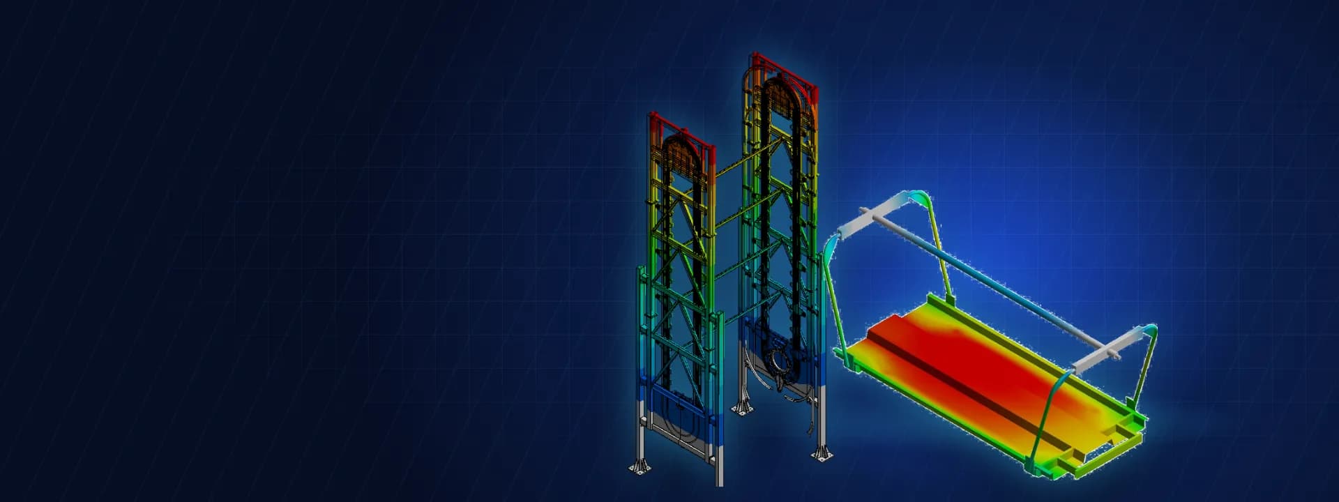
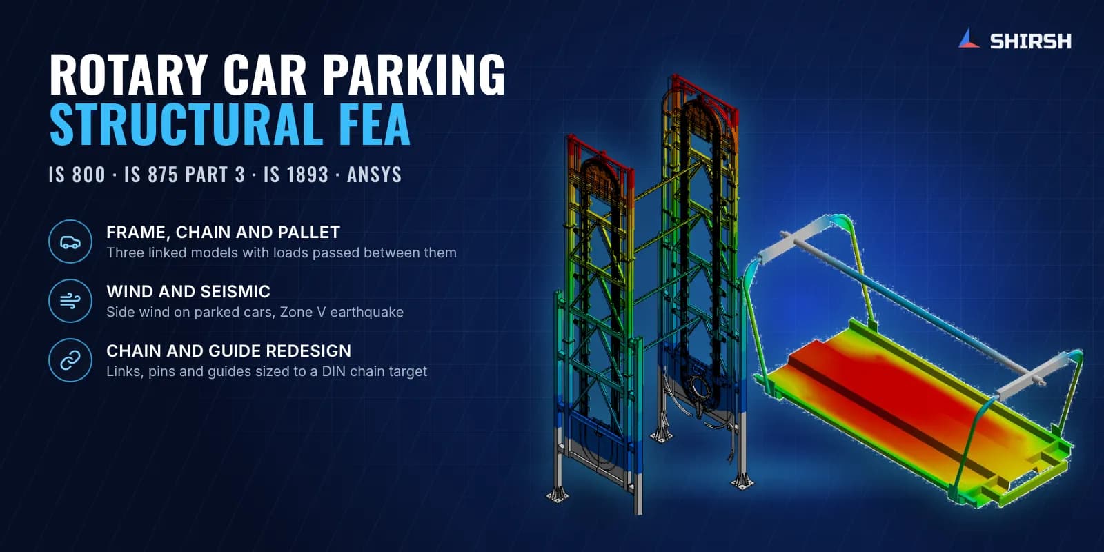
We split the system into three linked models so that each could be meshed properly. The drive shaft and the car pallet were modelled in full. The frame and chain assembly was modelled as a sectioned, symmetric solid and shell model with beam elements. Small holes, fillets and fasteners were removed, second-order elements were used, and an error plot confirmed the mesh was fine enough in the general regions.
Loads passed from one model to the next. Sprocket and gear torques from the maker's drive calculation went into the shaft model, and the shaft reactions then became inputs to the frame. On the pallet, the car weight was applied at the tyre contact patches. In the frame model, each car and pallet became an equivalent mass at its hanging point. Wind pressure on the exposed car surfaces was worked out to IS 875 Part 3, and seismic acceleration to IS 1893 for Zone V.
The frame was checked for four combinations of dead, live and mechanical load with earthquake or wind in each horizontal direction, plus a gravity and drive case. Allowable stresses followed IS 800 working stress design on the yield stress of each material. Lateral sway was compared with a height-based drift limit.
Where parts failed, we proposed changes and re-ran the model:
Thicker guide plates, larger high-strength guide wheel pins and a wider roller contact for the guide wheels.
A heavier channel for the guide fixture, thicker mirror guide plates and a tie between the middle frame beam and the guideway channels.
A guide mechanism at both ends of the chain loop and larger base columns to control sideways movement.
Anti-buckling support tubes under the pallet decking, rearranged after the first pallet run.
Thicker special chain links, a larger pin and a higher-strength steel to reach the DIN chain target.
A weld size recommendation at a frame stress concentration, plus anchor and base plate design using the reported support reactions.
Common questions
Why use FEA for a rotary car parking system instead of hand calculations? The load path runs through chain links, guide wheels, a drive shaft and a braced frame, and each part sees a different mix of gravity, drive torque, wind and earthquake load. Linked finite element models show where these combine and which part governs, which hand calculations cannot do reliably for this geometry.
Which Indian codes apply to the structure of a mechanical car parking tower? The steel frame can be checked to IS 800, with wind loads on the parked cars from IS 875 Part 3 and seismic loads from IS 1893. Chain safety for the moving parts is usually set by the machinery practice the manufacturer follows, which in this case was a DIN-based target.
Challenges we overcame
Load path from parked cars through pallets, chain links, guide wheels and shaft into a slender braced frame
Wind load acting on the sides of stacked parked cars
Earthquake design in the highest Indian seismic zone
Guide bosses and special chain links overstressed in the first round of analysis
Excessive sideways movement of the chain assembly and tower under side wind
A DIN-based chain safety target set by the client partway through the job
How we executed
- 1
Reviewed the maker's drawings, drive calculation and material list, and agreed loads and load combinations
- 2
Built three linked models for the drive shaft, the car pallet and the frame with chain assembly
- 3
Meshed with second-order solid, shell and beam elements and checked the error plot
- 4
Calculated wind pressure on parked cars to IS 875 Part 3 and seismic acceleration to IS 1893
- 5
Ran the shaft under drive torque and passed its reactions into the frame model
- 6
Checked every component against IS 800 working stress allowables and the sway against a drift limit
- 7
Proposed section, guide, chain and pallet changes and re-ran until all parts passed
- 8
Reported support reactions for the anchor, base plate and foundation design
Project outcome
Stresses in the shaft, pallet and frame with chain assembly came within the IS 800 allowables in all load combinations.
Sideways movement of the tower under wind and earthquake was brought within the drift limit with guides at both ends and larger base columns.
The redesigned special chain met the DIN-based safety target the maker had asked for.
The maker got clear section, material and weld recommendations for the guide, chain and pallet parts.
Plummer block and anchor reactions were handed over for the foundation and anchor design.
Project gallery
Where this lives
Software used
Related solutions
Industries
At a glance
We apply the same rigour to every engagement
Let us show you what's possible for your product.