Refinery Static Mixer CFD: Multiphase Mixing and Pressure Drop Before Supply
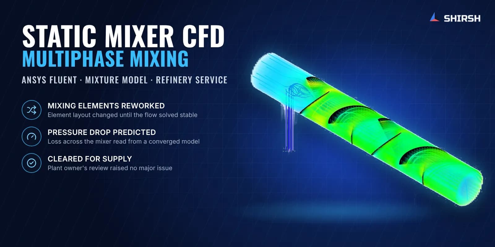
Multiphase CFD of a refinery static mixer in ANSYS Fluent. A reworked element layout gave a stable flow and the mixer was cleared for supply.
Project brief
A process equipment maker had an order to supply a static mixer to a refinery. The mixer brings a hot vapour stream from a regeneration section together with a recycled caustic liquid, and the refinery's tender asked for a CFD report on mixer performance before the unit could be supplied.
Shirsh Technosolutions carried out the static mixer CFD in ANSYS Fluent as a three-dimensional multiphase study. The first element layout would not give a stable flow solution at the specified line pressure, so we flagged it early, proposed other mixing element shapes and re-ran the model on the modified geometry. The revised design gave a converged flow field and a pressure drop prediction, and the refinery's engineering team reviewed the report and cleared the mixer for supply.
What was at risk
A static mixer has no moving parts. All the mixing comes from the elements fixed inside the pipe, which split, turn and recombine the flow. The same elements also cost pressure, and on a refinery line the process sets the line pressure and how much loss it can take.
Here the duty was harder than a single-phase blend. A large vapour stream enters along the pipe, and a much denser caustic liquid comes in through a side nozzle. The owner needed to know:
whether the liquid spreads across the full pipe section or runs along one side
what pressure drop the mixer adds to the line
whether the element layout behaves sensibly at the specified operating pressure, which could not be changed
The supplier also had a delivery commitment, so any change to the mixer had to be settled quickly and backed by analysis the owner would accept.
Solution offered
Model and mesh. The mixer was modelled in ANSYS SpaceClaim with the outer pipe, the side injection nozzle and the full series of mixing elements. The fluid volume was meshed with local refinement around the element edges and plates, where the velocity gradients are steepest, and near-wall resolution was checked before the runs.
Multiphase CFD in ANSYS Fluent.
Three-dimensional, steady-state, turbulent flow with the mixture multiphase model for the vapour and liquid phases.
Realizable k-ε turbulence with enhanced wall treatment, with mass, momentum and energy solved together.
Separate mass flow inlets for the main vapour stream and the injected caustic, a pressure outlet at the specified operating pressure and no-slip walls.
Fluid properties for both phases taken from the owner's process datasheet.
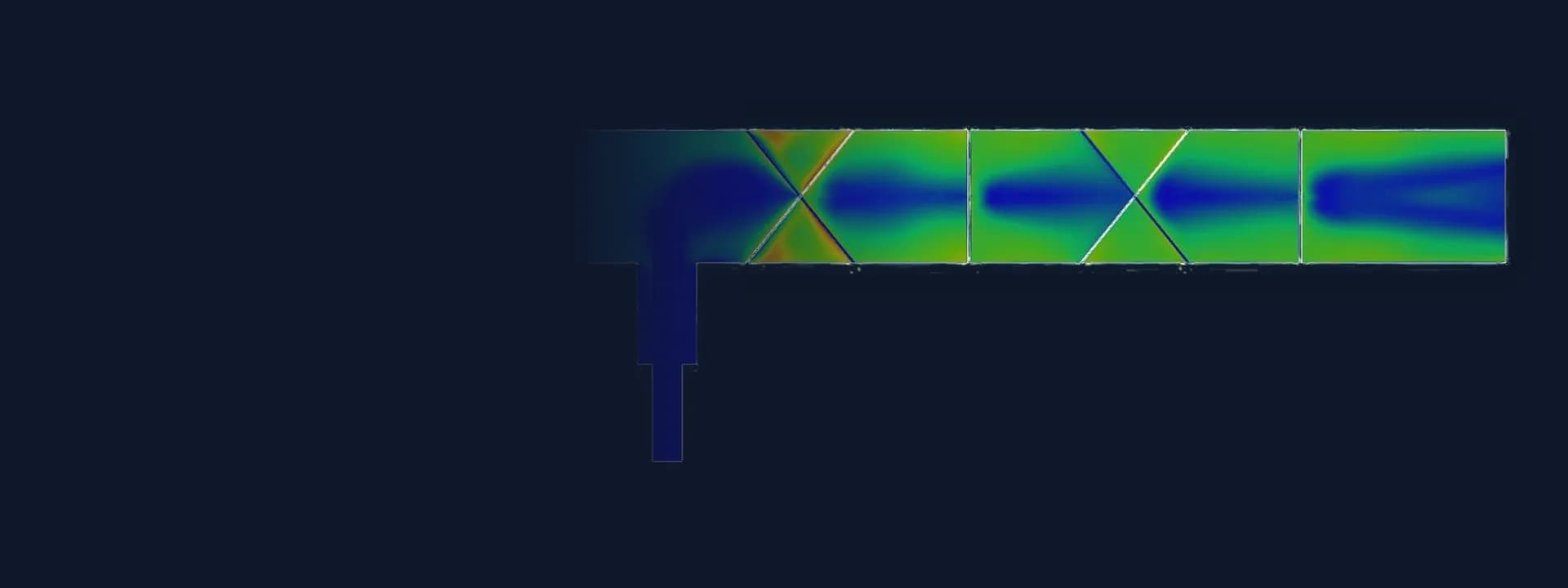
Design iteration. With the first element layout, the solution at the specified line pressure would not settle: the flow field diverged and the turbulence quantities could not be resolved. We reported this to the supplier and the refinery straight away, explained that changing the element configuration was the practical way forward, and suggested alternative mixing element shapes. The modified design uses pairs of crossed baffle plates alternating with half-disc segments, each set turned relative to the one before, so the flow is split and rotated as it moves along the pipe.
Results read for the owner. For the modified mixer we reported pressure and velocity contours, velocity vectors, profiles at several sections along the pipe, liquid volume fraction on cross-sections, streamlines of each stream and a volume rendering of the flow. The pressure drop was taken from the difference in total pressure between inlet and outlet, and the mass balance between inlets and outlet was checked to confirm convergence.
Common questions
What does a CFD study of a static mixer tell you? It shows how the injected stream spreads across the pipe, where the flow speeds up or recirculates around the elements, and how much pressure the mixer costs the line. Element shape, number and spacing can then be compared before the mixer is fabricated.
Why model a gas and liquid static mixer as multiphase? The two streams have very different densities, so a liquid injected into a vapour line behaves nothing like two gases blending. A multiphase model tracks each phase and shows whether the liquid really reaches the whole cross-section.
Challenges we overcame
A dense caustic liquid injected from the side into a large vapour stream
Pressure drop and line pressure fixed by the refinery process
A first element layout that would not give a stable solution at the specified pressure
A supply commitment that left little room for repeated redesign
Results that had to satisfy both the mixer supplier and the refinery's engineers
How we executed
- 1
Collected the mixer drawing and the process datasheet with stream properties from the supplier and the refinery
- 2
Built the 3D model of the pipe, injection nozzle and mixing elements in ANSYS SpaceClaim
- 3
Meshed the fluid volume with refinement around the elements and checked near-wall resolution
- 4
Solved steady, turbulent multiphase flow in ANSYS Fluent with the mixture model and realizable k-ε turbulence
- 5
Ran the specified line pressure, found the first layout did not converge and reported it to the supplier and the refinery
- 6
Proposed alternative mixing element shapes and modelled the modified layout of crossed baffles and half-disc segments
- 7
Re-ran the CFD and checked convergence through the mass balance between inlets and outlet
- 8
Reported pressure drop, velocity and pressure fields, phase distribution on cross-sections and streamlines for the owner's review
Project outcome
The modified element layout gave a stable, converged flow solution at the refinery's specified operating pressure.
The injected liquid spread across the pipe section and the phase distribution evened out along the mixer.
The pressure drop across the mixer was predicted from the converged model and reported to the owner.
The refinery's engineering team reviewed the CFD report, observed no major issue and allowed the supplier to proceed with supply.
Project gallery
Where this lives
Software used
Related solutions
Industries
At a glance
We apply the same rigour to every engagement
Let us show you what's possible for your product.