
FRP Composite Utility Pole Design: Layered Shell FEA for a 33 kV Line
FRP composite utility pole designed and checked ply by ply with layered shell FEA in CalculiX, for an unguyed pole on a rural 33 kV line.
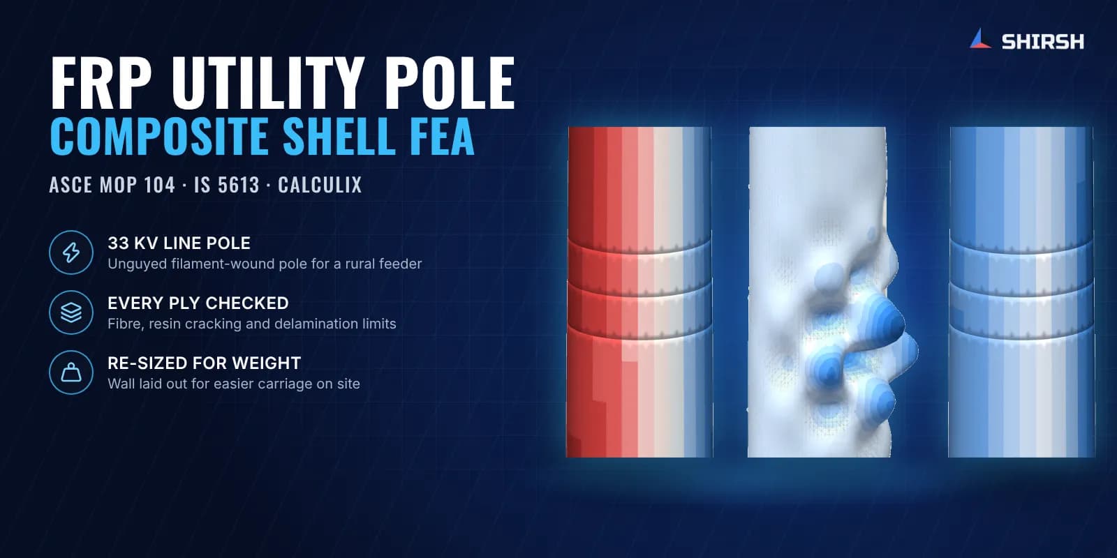
Project brief
An engineering consultancy working for a power distribution utility asked us to design an FRP composite pole to replace steel poles at the straight-run locations of a rural 33 kV line. Much of the route crosses farmland, and the utility wanted a pole light enough to be carried to each location by hand, so that trucks and cranes stay off the fields.
Shirsh Technosolutions took the job from load calculation to a verified pole. We worked out the loads from the utility's own line data, sized a filament-wound E-glass pole by hand calculation, and then checked the whole pole a second time with a layered shell finite element model in CalculiX, with every ply of the wall modelled the way it will be wound. When the client asked for a lighter pole, we re-laid the wall so that material sits only where the bending needs it, and verified the new layout ply by ply.
What was at risk
A composite pole does not fail like a steel one. The glass fibres carry the bending, but the resin between them can crack long before the fibres break, and a thin wall can wrinkle locally on the compression face before the pole runs out of strength. On a slender, unguyed pole the tip deflection in high wind often decides the section, not the stress. Every reduction in weight pushes on all of these limits at once.
The utility needed clear answers before any pole was wound:
Will an unguyed pole carry the conductor and wind loads for both conductor arrangements on the line, with the factor of safety the electrical inspector expects?
How far will the top move in the design wind, including on a hot day when the resin is softer?
Will the thin wall buckle locally, and will the layers split at the places where the wall changes thickness or where clamps bear on it?
How light can the pole be made before one of these limits is reached?
What must the band clamps, the hardware and the foundation be designed for?
The Indian line design code gives factors of safety for steel, concrete and wood supports but does not list FRP, so the design had to bring together the line code for loads and FRP utility pole practice for the laminate.
Solution offered
Loads from the utility's own data. Conductor tensions were taken from the utility's line analysis and carried from still air to the design wind by a change-of-state calculation. Wind on the conductors, the optical fibre cable, the crossarms and the shaft was built up height by height. Both conductor arrangements, erection, broken wire and handling cases were set up, and the attachment heights were transferred to the shorter pole so that clearances stay as the utility intended.
Design basis. Loads to IS 802 and IS 875 (Part 3) within the line design code IS 5613. Laminate design to ASCE Manual of Practice 104 and ANSI/ACMA UP01 for FRP utility poles, with the factor of safety applied to the allowable stress. Vortex shedding checked to EN 1991-1-4.
Hand calculation first. The pole was sized as a tapered, second-order beam fixed at the ground line, with the allowable stress taken as the lower of fibre strength and local shell buckling. This gave the wall thickness, the extra build-up in the buried zone and at the hardware fixings, and the deflection under the design wind.
Layered shell FEA in CalculiX. The full pole, buried length included, was modelled with composite shell elements in CalculiX, an open-source implicit solver. Each band of the wall schedule has its own ply stack of helical and hoop layers, so the ground-line build-up, the ply drops and the build-ups at the fixings are all present as they will be wound.
Model generated by script from the same calculation file as the drawing, so nothing is typed in by hand and the model can be re-run on any change.
Buried length on lateral soil springs at soft, medium and stiff values, plus a fixed-base run for the deflection check.
Conductor and hardware loads applied through narrow rings at the clamp positions, the way a band clamp loads the pole.
Large-deflection analysis in every static case, with eigenvalue and nonlinear buckling runs and a modal analysis with the hardware and conductor mass.
Model checked against hand values for mass, a tip load test and support reactions before any result was used.
Failure checked ply by ply. Fibre failure by maximum stress with Hashin as a cross-check. Resin cracking by the Puck criterion (VDI 2014), with Hashin, Tsai-Wu and maximum stress as cross-checks, kept out of the service load range and accepted only in the rare design storm. Interlaminar shear and peel at the ply drops were checked in a detailed 2D submodel of the wall. A hot-pole case with reduced resin-dominated stiffness was run on the same checks.
Common questions
Why use layered shell FEA for an FRP pole when a beam calculation gives the stress? A beam calculation gives the average stress in the wall. A composite wall is made of plies at different angles, and the resin between them can crack, or the layers can separate at a change of thickness, while the average stress still looks comfortable. A layered shell model checks each ply against its own failure modes and shows local buckling of the thin wall directly.
Is CalculiX reliable for composite structural analysis? Yes, when the model is verified. CalculiX is a mature open-source implicit solver with composite shell elements. In this job the shell model was checked against hand values for mass, tip deflection and reactions, and it agreed closely with the independent hand calculation on both stress and deflection.
Challenges we overcame
Tip deflection in high wind, rather than strength, deciding the section of a slender unguyed pole
Resin cracking and delamination limits that a beam calculation cannot see
Local wrinkling of a thin wall on the compression face near the ground line
A weight target for manual carriage that pushed every limit at once
FRP not listed in the Indian line design code, so line loads and FRP laminate practice had to be brought together
How we executed
- 1
Collected the utility's line analysis, conductor data, wind basis and standard line drawings
- 2
Calculated conductor tensions at the design wind and built up the loads on the shorter pole
- 3
Sized the pole by a second-order tapered beam calculation with buckling-limited allowables
- 4
Generated a layered composite shell model of the full pole in CalculiX from the design calculation
- 5
Verified the model against hand values for mass, a tip load test and support reactions
- 6
Ran strength, deflection, buckling, hot-pole, broken-wire, erection and modal cases on soil springs and with a fixed base
- 7
Checked fibre failure, resin cracking and interlaminar stresses ply by ply, with a 2D submodel at the ply drops
- 8
Re-laid the wall for lower weight and issued clamp requirements, hardware loads and foundation reactions
Project outcome
The unguyed FRP pole met the strength, deflection, buckling and service requirements of the design basis for both conductor arrangements.
The shell model and the hand calculation agreed closely on both stress and deflection, giving two independent checks of the same pole.
Resin cracking was kept out of normal service loads, and the layers stayed well clear of splitting at the ply drops and under the clamps.
Tip deflection was identified as the limit on further weight reduction, which gave the utility a clear basis for its weight decision.
The utility received clamp requirements, hardware interface loads and foundation reactions for its other vendors.
Project gallery
Where this lives
Related solutions
Industries
At a glance
We apply the same rigour to every engagement
Let us show you what's possible for your product.